November 1, 2023
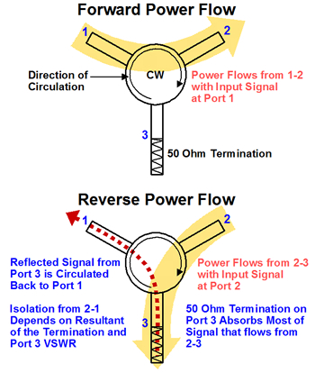
A junction circulator is a 3-port device that permits flow of microwave energy in one direction only, e.g. from port 1 to 2, 2 to 3, and 3 to 1. Each port is connected to one arm of a symmetrical Y junction that is coupled to magnetically biased ferrite material. When one of the ports is terminated (matched condition) the other two ports are isolated in the reverse direction. Thus an isolator is a circulator with a matched termination, usually integral to the unit, and by convention on port 3.
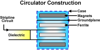
Figure 1
The ferrite circulator is the basic building block of the ferrite components described in this catalog. More complex functions and/or improved performance can be obtained by combining basic junctions. Applications for circulators and isolators include coupling elements for amplifiers, diplexers and phase lock injection circuits.
Figure 1 provides a schematic construction of a typical circulator. Only one of the three strip line ports is shown. In practice there are no air gaps inside the case. The biasing magnetic field direction is axial (vertical in diagram) through the ferrite disks, and returns through the steel case. Other designs use an aluminum case for the core, and steel cladding to complete the magnetic return path.
SELECTING THE DEVICE
The most misunderstood concept of circulators is that of isolation. Circulators do not provide isolation until one of the ports is terminated. Then the isolation between the other two ports (in the direction opposing the direction of circulation) is approximately equal to the return loss due to any mismatch on the terminated port. This basic relationship is shown in Figure 2.
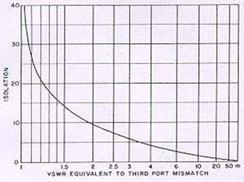
Figure 2
An isolator may be used for reducing the Voltage Standing Wave Ratio (VSWR) as shown in Figure 3. The input VSWR vs. load VSWR is shown for a number of different degrees of termination match.
Assuming that Port 3 is terminated by a perfect 50 Ohm termination, the isolation is simply a function of the circulator VSWR. In order to achieve a given amount of isolation, it is necessary to select a circulator that is sufficiently well matched to meet the requirements. Practical limitations such as bandwidth and temperature range restrict isolation from a single junction to between 20 and 25 dB. Higher values of isolation are obtained by cascading junctions. For example an isolator with two junctions would give typically 50 dB of isolation, and would be called a 4-port device (2 of the 6 ports are connected internally). When an isolator is used, consideration must be given to the power handling capability of the integral termination supplied.
Figure 4 gives the input power rating (as a multiplier of termination rating) vs. load VSWR.
Isolator terminations are rated at standard values of 5, 10, 30, 50, 70 and 100 Watts. For information on other values and even higher power terminations, consult the factory.


Figure 4 gives the input power rating (as a multiplier of termination rating) vs. load VSWR.
Isolator terminations are rated at standard values of 5, 10, 30, 50, 70 and 100 Watts. For information on other values and even higher power terminations, consult the factory.
UNDERSTANDING COAXIAL AND DROP-IN CIRCULATORS AND ISOLATORS
Discussion of the following topics is necessary to understand the operation of junction circulators:
FERRITE REGION
MAGNETIC CIRCUIT
IMPEDANCE TRANSFORMATION
TRANSMISSION LINE GEOMETRY
CONNECTORS
FERRITE REGION
Circulation and isolation are caused by the ferrite material, which is a dielectric with magnetic properties. The ferrite region consists of two ferrite disks which are placed either side of the stripline Y junction. These disks form a dielectirc resonator. When power is applied from any of the three transmission lines, a standing wave pattern is established. This electromagnetic field pattern is due to a pair of mathematically identical counter-rotating waves, with a maximum at the input port, and nulls at 90° from the input port. The standing wave pattern is symmetrical with respect to the input port if there is no applied magnetic field, and energy is transferred equally into the other two ports, as shown in Figure 5A.

The degree of coupling or isolation from the resonator are determined by the relative position of a given port and the standing wave pattern. For example, if a port were situated at a null in the standing wave, there would be no power transfer to that port.
The presence of an axial magnetic field across the ferrite material changes the effective permeability seen by the rotating waves, but in a direction that depends on the sense of rotation. The result is the two waves are no longer identical, and are split into two mathematical solutions having different radial velocities. This causes the standing wave pattern to be rotated from its symmetrical position. The desired power transfer and isolation properties are obtained by designing the circulator so that the standing wave pattern is rotated 30°. With power applied to port 1, the next port in the direction of rotation (port 3) is isolated from the resonator, whereas port 2 is fully coupled to the resonator (as shown in Figure 5B). In practice, circuit tuning can be used to compensate for small misalignment of the rotation standing wave pattern.
When a ferrite material is magnetized, the magnetic moments of the electrons precess (wobble like a spinning top) at a frequency proportional to the biasing magnetic field. Ferrimagnetic resonance occurs when a rotating radio frequency (RF) magnetic field has the same direction and frequency as the precessing electrons in the ferrite material. The maximum coupling of the energy from the RF signal to the ferrite material will occur at a specific frequency, known as ferrimagnetic resonance. If the direction of rotation or the frequency of the RF signal is changed, coupling will decrease. A simplistic analogy can be used to explain this phenomena. It is easier for a person to pass items to an individual riding on a merry-go-round if he is running in the same direction and at the same speed, while it is more difficult to pass items if they are moving at very differnet speeds or in opposite directions.
However it is not desirable to magnetically bias the junction circulator so that ferromagnetic resonance occurs at the operating frequency because the device would be extremely lossy. High insertion loss can also occur at very low biasing magnetic fields. This low field loss region arises because the applied magnetic field is not sufficient to fully saturate or align the individual magnetic domains of the ferrite material. Although high loss occurs in both the low field and ferromagnetic resonance areas, low loss operation can still be obtained in the below and above resonance regions (as shown in Figure 6).
COMPARISON OF ABOVE & BELOW RESONANCE CIRCULATOR DESIGNS
It should be noted that the following comparison applies principally to strip line junction circulators and is intended as a guide only. Also, the meaning of above or below resonance is with respect to the magnetic field, not the operating frequency.

OPERATING FREQUENCY
Above resonance (A/R) circulators can be designed to operate from 50 MHz to approximately 2.5 GHz. Although operation above this frequency can be achieved, impractical magnetic circuits are required in order to bias the ferrite material. Operation at frequencies below 50 MHz is difficult because the magnetic field and the demagnetizing factors of the ferrite geometry do not allow proper biasing of the junction.
Below resonance (B/R) circulators are generally limited to operation above 500 MHz. Operation below this frequency is possible, but generally more limited in performance. As the frequency is reduced, the B/R region of operation diminishes (as shown in Figure 7). The lower magnetic field required for operation of the B/R junction is not sufficient to fully saturate the ferrite material, resulting in the low field loss region.
The low field loss and ferrimagnetic resonance regions merge together, thereby reducing or eliminating entirely the B/R region for low loss operation. The B/R junction can operate at frequencies up to approximately 30 GHz. Operation above this frequency is limited mainly by the stripline geometry. Waveguide circulators can be designed to operate at frequencies greater than 100 GHz.

BANDWIDTH
B/R junction characteristics allow broad bandwidth operation up to 100%. The A/R junction is generally limited to 40% maximum bandwidth.
TEMPERATURE
The A/R circulator can be temperature compensated using special magnetic materials. The magnetic properties of these materials change with temperature and are used to compensate for the ferrite junction temperature characteristics. Above 1 GHz, operation over a temperature range of -54 to +95°C is common.
The B/R junction is virtually limited to room temperature operation below 1 GHz. The magnetic properties of the ferrite materials available to build devices at these frequencies are extremely temperature sensitive. Available materials have Curie temperatures less than 100°C. The Curie temperature is defined as the temperature at which the ferrite material’s magnetic characteristics are reduced to zero. Circulation of the input signal cannot occur at this temperature. In general, ferrite materials used for the higher operating frequencies have greater temperature stability. Operation above 4 GHz and from -54 to +85°C can be obtained, depending on the bandwidth and the level of performance desired.
The temperature performance of the B/R and A/R circulators can be improved by the use of temperature compensating materials in the magnetic circuit.
JUNCTION SIZE
The ferrite disk diameter for a given frequency is a function of the effective permeability and dielectric constant of the ferrite junction. The A/R junction has a greater effective permeability than the B/R junction because of the higher internal magnetic biasing field and ferrite saturation magnetization value. The ferrite disk in the A/R junction will therefore be smaller than the B/R junction for the same operating frequency. For narrow bandwidths in the 1.0 GHz to 2.5 GHz range, the A/R junction circulator is usually smaller.
MAGNETIC CIRCUIT
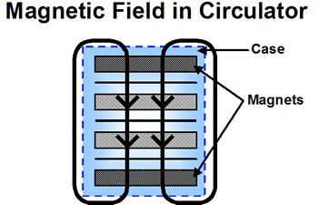
High energy-product magnets are now used to bias the ferrite junction, minimizing the problem of irreversible change in the magnetic field due to temperature. Extensive temperature cycling is no longer required to stabilize the magnetic field against further permanent change. As previously discussed, the magnetic circuit will also include materials to compensate for the reversible changes with temperature. However, optimization of the magnetic circuit can be done to provide additional magnetic shielding for critical applications where units are mounted in very close proximity. A steel case provides a return path for the magnetic field (as shown in Figure 8). The magnetic field is largely contained, so that adjacent units do not interfere.
IMPEDANCE TRANSFORMATION
Multiple quarter-wavelength sections of transmission line are commonly used to match the lower impedance of the ferrite disk to the 50-Ohm impedance of the connectors and connecting lines. The VSWR and bandwidth specifications determine the number of transformer sections required. A typical VSWR specification for a circulator is 1.25:1. For narrow bandwidths (less than 5%), the ferrite junction impedance can be designed to be 50 Ohms. Matching transformers are not required for this type of design, which allows a small package size to be obtained. The impedance characteristic of this junction is shown in Figure 9A.

Moderate bandwidths (less than 40%) can be obtained for both the A/R and B/R junctions by using a single-section transformer external to the ferrite disk. The transformer length can be shortened by using high dielectric materials and meandering the circuit. The single-section transformer also can be designed to be included within the ferrite region. Although a more compact size can be obtained, the bandwidth using this technique will be on the order of 25%. The impedance characteristic of the single-section design is shown in Figure 9B.
Bandwidths greater than an octave can be obtained for the B/R junction by using two or three external transformer sections. Using more than three transformer sections provides little improvement in performance, due to the limitations of the ferrite junction. The A/R ferrite characteristics limit its operation to the previously discussed 40%. The typical two-section transformer impedance characteristic is shown in Figure 9C.
Lumped element circulator designs replace the quarter-wavelength transformer sections with discrete capacitors and inductors to achieve small package sizes in the frequency range of 50 MHz to 1.0 GHz. These devices are temperature sensitive and operate over narrow bandwidths at low power levels.

TRANSMISSION LINE GEOMETRY
Balanced stripline is the most common transmission line geometry in use for the circulator junction, and is used for coaxial and drop-in form factors.
CONNECTORS
Various connector types can be supplied on circulators. SMA male or female connectors are the most popular and in general the easiest to install. TYPE N, TNC, and right angle connectors of various types also can be used. Some connectors, however, cause limitations in the electrical performance of the high frequency and broad bandwidth circulators.
The package size may have to be increased to accommodate certain connector types. For example, a 0.50-inch thickness package will not accommodate a TYPE N connector without an increase to at least 0.63 inch. Circulators requiring the use of high voltage connectors such as HN or the larger EIA 7/8, 1-5/8 or 3-1/8 types use an intermediate adapter so that they can be installed on the circulator.
Another connector configuration can be obtained by mounting the circulator on a waveguide adapter. These devices are known as Isoadaptors, in which the large waveguide section provides a rigid base for the usually smaller coaxial circulator. These units are particularly useful when both waveguide and coaxial connectors are required. For example, the waveguide port can accept a signal directly from a waveguide antenna, while the output from a SMA connector port can be fed directly into a solid-state amplifier.
Circulators can be supplied with removable connectors. The connector shell can be removed to allow the center conductor to be directly soldered to a circuit board. High temperature solder is used for the internal solder joint so the pin will not move while being soldered to the board.
For many applications circulators are designed without connectors so that the junction circuit tabs can be soldered directly to a circuit board. This type of component is known as drop in. Careful consideration must be given to the grounding of the circulator housing as well as the geometry of the mating substrate. It is essential that the circulator manufacturer be supplied with as much information as possible on how the unit will be integrated into the final assembly. The manufacturer’s test fixture should be used to improve the correlation of measured data.
DESCRIPTION OF OPERATING PARAMETERS
VSWR: This parameter specifies to what degree the input signal will be reflected back toward the source. For critical applications, the magnitude and phase of the reflected signal can be provided as an impedance plot recorded on a Smith Chart.
INSERTION LOSS: When a signal is applied in the low loss direction to the circulator, the insertion loss will be the ratio of the output signal to the input signal, expressed in dB.
ISOLATION: An isolator is a two-port device made by internally terminating one port of a circulator (as shown in Figure 10). When a signal is applied in the high loss direction to the isolator, the isolation will be the ratio of the signal applied to the output port (2) to the signal measured at the input port (1), expressed in dB. It also should be noted that in the case of a circulator, this parameter is not applicable.
The parameters of isolation, VSWR, and insertion loss are required to specify an isolator, whereas a circulator is completely defined by only the VSWR of the three ports and its insertion loss. Although a circulator can be made into an isolator by terminating one port, it does not have an intrinsic isolation value. The isolation measured is dependent on the VSWR of both the termination and the circulator port.
Example: A circulator has a measured VSWR of 1.22 for all three ports. If a perfect test termina-tion with a VSWR equal to 1.00 were available to place on Port 3, the resulting isolation from Port 2 to Port 1 would be 20 dB. If a test termination with a VSWR equal to 1.05 were placed on Port 3, the resulting isolation from Port 2 to Port 1 would vary between 18.2 and 22.5 dB depending on the phase difference between the two VSWRs. The resulting isolation value is a function of the VSWR of the test termination and the relative phase of the VSWR on the circulator port.
PERCENTAGE BANDWIDTH: Expressed as the difference between the high and low operating frequencies divided by the center frequency multiplied by 100, this parameter is useful when comparing the relative performance of various devices.
OPERATING TEMPERATURE RANGE: The temperature range at which a circulator must meet all specifications.
STORAGE TEMPERATURE RANGE: The temperature range at which a circulator must survive without permanent degradation in spec-ifications. Storage temperatures from -60 to +125°C usually can be accommodated.
PHASE TRACKING: Phase tracking is a measurement of the variation of the electrical length between the input and the output ports of two or more circulators. The insertion phase of the A/R circulator is very sensitive to changes in the magnetic biasing field. This effect can be used to magnetically trim the phase. Some degradation in VSWR or isolation may be required to allow this method of trimming to be used. The insertion phase of the B/R circulator cannot be easily adjusted.
PHASE LINEARITY: This parameter is defined as the deviation from a best fit straight line of insertion phase versus frequency. For A/R and B/R circulators with less than 20% bandwidth, the phase linearity will generally be within two degrees.
IMPEDANCE CHARACTERISTIC: This parameter describes both the magnitude and phase of the reflected signal recorded as an impedance plot on a Smith Chart. Applications such as amplifiers and voltage-controlled oscillators (VCOs) may require the reflected signal to have a minimum phase variation with frequency. The basic input impedance characteristic of a circulator will be one of the three types as shown in Figure 9. The phase change is proportional to the number of transformer sections used to obtain a given bandwidth. For moderate bandwidths, it is possible to restrict the phase change to less than 360 degrees.
BREAKDOWN: The peak power breakdown value of a circulator is reduced by an increase in load mismatch, altitude, temperature, or pulse width. A mismatch on the output port will reflect a percentage of the signal back into the circulator, causing a higher internal voltage level that will reduce the power rating of the circulator. The peak power rating can be increased by filling the internal volume of a circulator with a high dielectric strength material. Hermetically sealed modules can be used to maintain pressurization for operation at high altitudes.
LIMITING: Another effect related to the peak power rating of a circulator is known as the non-linearity or peak power threshold of the device. As the peak power level increases beyond a critical value, the loss versus magnetic field curve will show considerable changes in the region below the main resonance. The A/R region will remain essentially unaffected. (as shown in Figure 11)
The peak power threshold is dependent on the junction geometry, bandwidth, and ferrite material properties. The threshold level can be improved by doping the ferrite material with elements such as holmium, which will cause a slight increase in the insertion loss at low powers.

DISTORTION PRODUCTS: At high peak power levels, the non-linearity of the circulator generates harmonic and intermodulation products within the ferrite junction. Because of design limitations imposed by other parameters, it is difficult to eliminate this effect.
AVERAGE POWER: The power dissipated in the circulator is in proportion to the insertion loss. If the average power level is significant, the dissipated power will cause heating of the ferrite junction and degradation in performance. Conduction, convection or liquid cooling can increase the average power rating of a circulator. The connector type is also important when the average power is significant. Captured SMA and hermetic seal connectors are limited in power rating because of their internal losses. The average power rating of a circulator will also depend on the resultant mismatch at the output port. For example if a signal of 100 W average power were applied at the input of a circulator terminated with a 6.00:1 mismatch, 51 Watts would be reflected, requiring the circulator to handle 151 watts total.
ISOLATOR TERMINATION RATING: The power rating required for the termination of an isolator depends on the mismatch on the output port, as shown below.
Mismatch on Output
% Power Reflected
RFI: Radio frequency interference (RFI) leakage values of 30 dB or less are easily obtainable in a standard package. Conductive epoxy can be used to seal the unit so that values over 60 dB can be obtained. Additional RFI shielding can be provided by utilizing special packaging techniques.
BIBLIOGRAPHY
Bosma, H., “A general model for junction circulators; Choice of magnetization and bias field,” IEEE Trans Magazine, vol. MAG-4, Sept. 1968, pp.587-596.
Bosma, H., “Junction circulators,” in Advances in Microwaves, vol. 6, Leo Young, Ed. New York: Academic, 1971.
Fay, C. E. and R. L. Comstock, “Operation of the ferrite junction circulator,” IEEE Trans. Microwave Theory Tech. (1964 Symp. Issue), vol. MTT 13, Jan. 1965, pp. 15 27.
Helzajn, J., “Frequency response of quarter wave coupled reciprocal strip line junctions,” IEEE Trans. Microwave Theory Tech., vol. MTT 21, Aug. 1973, pp. 533 537.
Konishi, Y., “New theoretical concept for wide band gyromagnetic devices,” IEEE Trans. Magazine (1972 Intermag Conf), vol. MAG 8, Sept. 1972, pp. 505 508.